Decapod Stereo 3D Equipment Guide
Table of Contents
Generic Hardware Components Required
The following table lists the generic hardware components required for stereo 3D imaging. The main requirement is that the setup be sturdy enough such that it does not move or fall over during image capture, and it must provide a sufficient level of adjustability for initially positioning the cameras over the content.
|
What? |
How? |
Why? |
|---|---|---|---|
1 |
Main Support |
Tripod or sturdy mounting surface |
To support camera setup such that it does not move during image capture. |
2 |
Intermediate Component |
Horizontal center column on tripod or articulating arm or ball head |
Allows for mounting of cameras in horizontal position (i.e. pointing straight down); may provide distance between tripod and cameras thus creating more space in which to set up the item being captured; provides some adjustment of camera position. |
3 |
Camera Mounting Stereo Bar |
A variety of off-the-shelf stereo bars or DIY mounting plate |
Provides a sturdy mounting surface for two cameras to sit side-by-side; allows some adjustment of camera positions during calibration. |
4 |
Pair of matching cameras |
Most cameras can be used for stereo capture as long as they meet the minimum requirements |
Two cameras help create a 3D image of a book surface which can then be dewarped. |
Additionally, users will need:
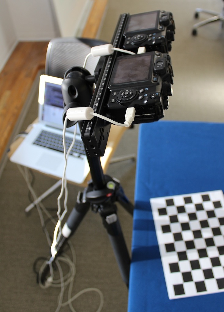
- Two USB cables to connect the cameras to Decapod if using tethered capture.
- A solid, brightly coloured background (i.e. bright green, or bright blue) to photograph against.
- A coloured stick, pipe cleaner, or piece of string that is distinctly a different colour than the book content and background (i.e. bright red). This will act as a page separator and be placed down the spine / gutter of the book as it is photographed.
Stereo Camera Selection
Almost any camera can be used for stereo capture as long they meet the following requirements:
- 2 identical cameras
- 10 MP or higher recommended
- If using interchangeable lenses, a standard lens 24mm, 30mm, or 35mm is recommended
If the cameras are to be tethered to Decapod, then there are additional requirements. See Appendix: Camera Selection.
Stereo Bar Selection
Cameras to be used in stereo 3D capture are mounted side by side, and face the same direction. To make mounting of stereo cameras easier, “stereo bars” can be acquired from camera equipment retailers. For additional information about stereo bar models and vendors, see Appendix: Stereo Bar Vendors.
When selecting a stereo bar, consider the following:
- ability to adjust distance between cameras and to adjust camera pan angle (note: space between cameras may be required so USB cable can be attached)
- weight (lighter is better for travel/convenience but heavy-duty will be required to support larger cameras)
- ease of mounting cameras and of mounting stereo bar to support system (tripod or other)
A stereo bar can also be made if these items are not readily available. Instructions on how to make a custom stereo bar can be found under Appendix: Do-It-Yourself Stereo Bar Solution.
Mounting Stereo Cameras
When mounting on the stereo bar, the cameras should be closely adjacent as possible and facing perpendicular (90 degrees) to the subject.
Stereo camera position examples:
Good position: cameras are close together and perpendicular to surface.
Poor position: both cameras are angled differently and not perpendicular to the surface.
Poor position: one camera is perpendicular to the surface, but the other is not.
Poor position: cameras are too far apart.
Stereo 3D Setup Examples
Note: more information about the hardware components mentioned in this section can be found in the Appendix.
Example 1: Tripod with Horizontal Center Column + Stereo Bar
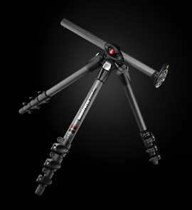
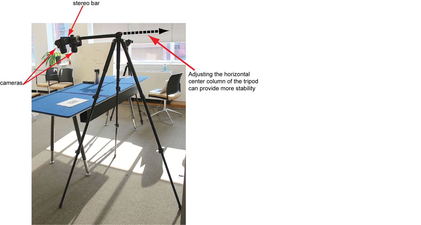
If using a tripod with an adjustable horizontal center column, like the Manfrotto 190XProB shown below, the stereo bar can be mounted directly to the end of the center column and no additional intermediate hardware is required.
Picture: Manfrotto 190XProB Tripod with horizontal center column.
Care must be taken to balance the tripod so that it does not tip over once the weight of the cameras and stereo bar is added. Adjusting the horizontal column to have a greater portion of its length on the side opposite the cameras will help; hanging a balancing weight on its end will provide further stability.
Begin by opening and extending the tripod legs into a wide base to provide maximum stability. Keeping the center column in a vertical position for now, mount the stereo bar to the tripod by threading the upper mount into the corresponding hole on the stereo bar. If the threaded hole in the stereo bar is larger than the tripod mount (typically ⅜”) it may be necessary to insert an adapter collar into the stereo bar mounting hole. For stereo bars with non-threaded holes or slots, a nut will be required to secure the stereo bar in place.
Once the stereo bar is secured to the tripod, mount the cameras onto the stereo bar. For stereo bars with threaded mounting bolts, insert each bolt in turn into the threaded hole on the bottom of the camera and tighten until secure.
For stereo bars without threaded mounts and with open holes or slots, separate bolts will be required (¼” diameter in most cases). The bolt must be long enough to thread fully into the camera mounting hole but not too long such that it cannot be firmly tightened against the stereo bar. We recommend that washers and/or rubber pads also be used. In this case insert each bolt in turn through the hole or slot in the stereo bar and thread it into the bottom of the camera until secure. Repeat for the second camera. Note that minor adjustments to the position of the cameras will be made during the calibration process; the cameras can be roughly positioned at this time.
Once the cameras are securely mounted to the stereo bar, carefully slide the center column all the way up. Ensuring that the tripod is stable, release the center column by pressing the release button. Adjust the level of the center column until it is in a fully horizontal position. At this point adjustments should be made to ensure that the tripod is stable including sliding the center column out and/or adding a balancing weight as described above.
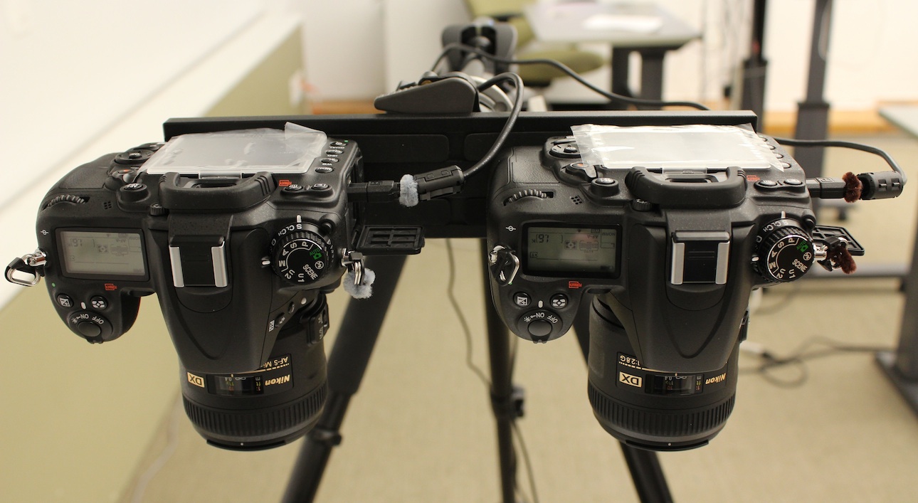
Picture: Front view of setup.
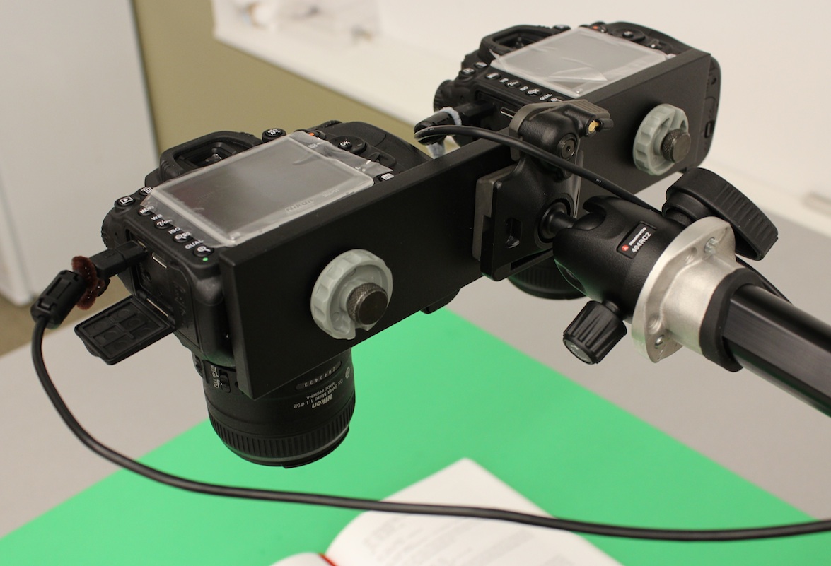
Picture: Rear view of setup.
Example 2: Tripod + Articulated Arm + Stereo Bar
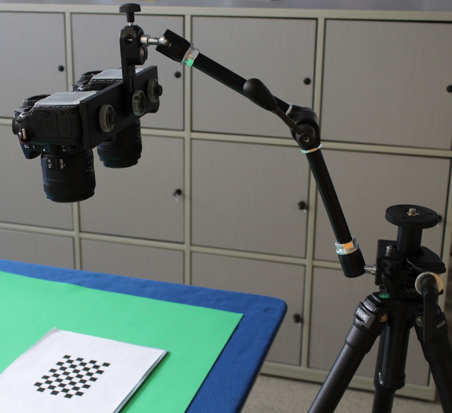
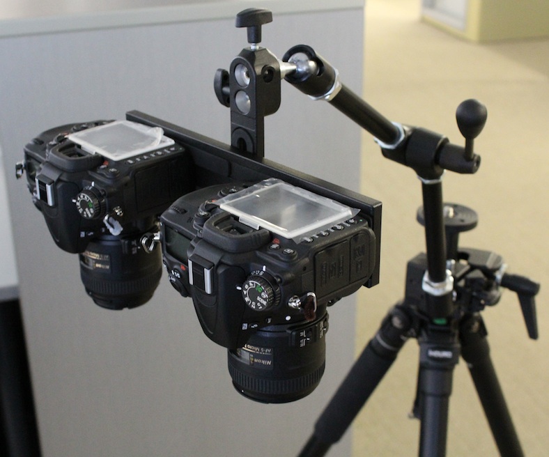
When using a tripod without a horizontal center column, an articulating arm such as the Manfrotto 143N Magic Arm Complete can be mounted to the center column of the tripod using a heavy-duty clamp such as the Manfrotto 035RL Superclamp.
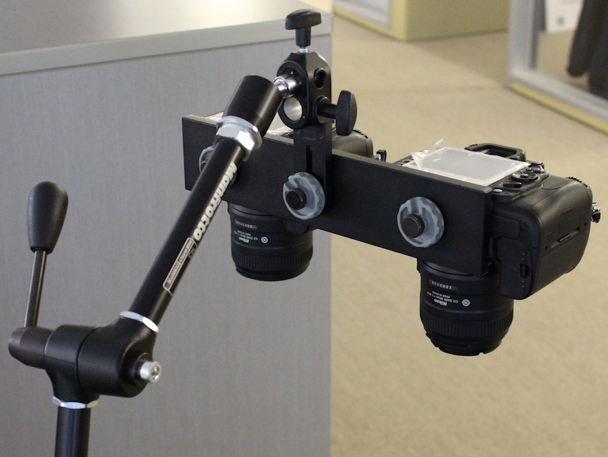
The articulated arm provides an excellent range of adjustability when positioning the cameras. The selected stereo bar is then mounted to the end of the articulating arm using the Camera Bracket 143 BKT (supplied with the 143N Magic Arm Complete). The mounting bolt supplied with the 143BKT bracket is 1/4" diameter; if the selected stereo bar has a larger threaded hole (typically 3/8"), an adapter collar will be required (readily available at camera equipement vendors).
Care must be taken to ensure that the tripod remains stable under the weight of the cameras, mounting bar and articulating arm. Using a lighter stereo bar will help. In addition, the Magic Arm has a central locking mechanism which locks all 3 joints of the arm at once; when the locking mechanism is released, note that all three joints will release at once. It is important to support the cameras and mounting bar when releasing the locking mechanism.
We recommend that the articulating arm is mounted to the tripod first. Keeping the arm in a fully vertical position, mount the stereo bar to the arm, then mount the cameras to the stereo bar. Taking care to support the entire assembly, release the locking lever of the arm and adjust all three joints at once until the cameras are in a horizontal position. Further adjustments will be made during calibration.
Picture: View of calibration setup with articulating arm clamped to the tripod.
Picture: Front view of setup with articulating arm clamped to tripod.
Picture: Rear view of setup showing the mounting bolts on the Manfrotto stereo bar and bracket.
Example 3: Tripod + Ball Head + Stereo Bar
The stereo bar can be mounted directly to a ball head which in turn is mounted directly to the tripod. The ball head makes it possible to point the cameras downwards at the surface of the book or other item being captured, without the need for a horizontal center column on the tripod. However in this case the area of capture will be somewhat limited since the cameras will remain close to the tripod center.
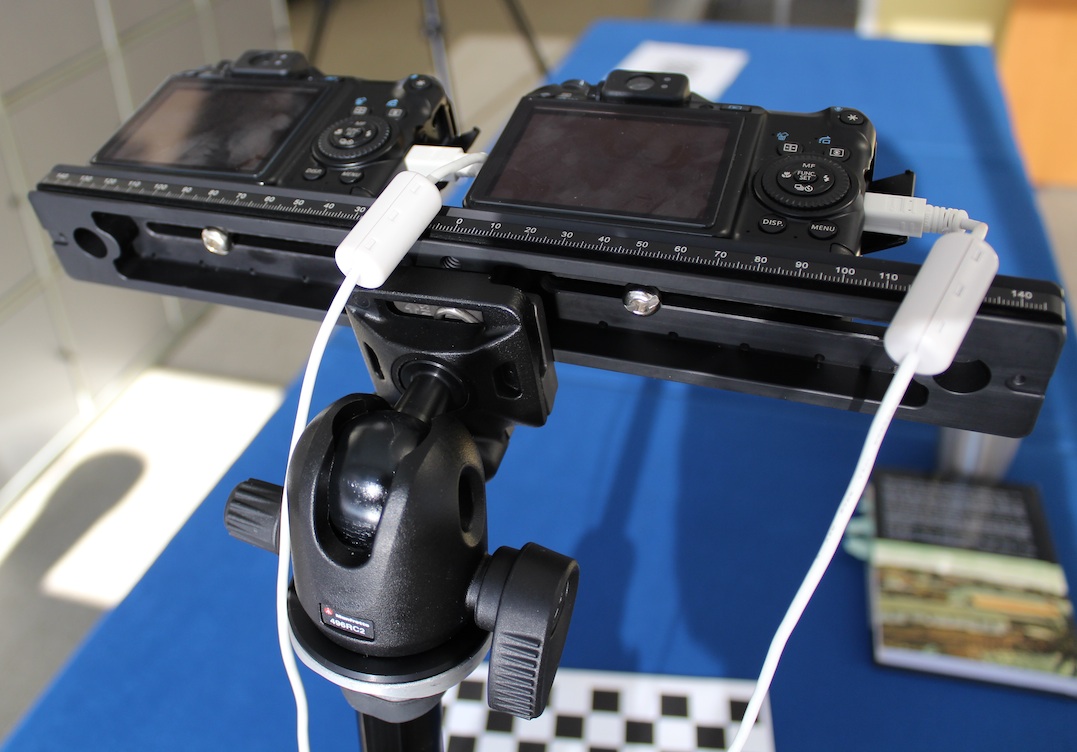
The ball head is mounted to the tripod by threading it onto the tripod mount. The three set screws on the underside of the tripod collar can then be tightened in order to provide further locking of the ball head in place. The stereo bar is then mounted to the ball head, and while in a vertical position the cameras are mounted to the stereo bar. Once the assembly is complete the position of the cameras can be adjusted.
Picture: Full view of setup showing Sunway stereo bar.
Picture: Close view of setup with Sunway stereo bar.
Example 4: Tripod with Horizontal Center Column + Ball head + Stereo Bar
For increased flexibility in camera positioning a ball head can be mounted to a tripod with a horizontal center column. The set up will be similar to that described in Example 1 "Tripod with Horizontal Center Column + Stereo Bar" but with the addition of a ball head on the end of the center column. Follow the instructions in Example 3 "Tripod + Ball Head + Stereo Bar" for mounting the ball head to the tripod and the stereo bar to the ball head.
Example 5: Articulating Arm + Stereo Bar
As an alternative to using a tripod, an articulating arm such as the Manfrotto 143N Magic Arm can be clamped directly to a sturdy table or other surface using a heavy-duty clamp such as the Manfrotto 035RL Superclamp. Once the arm is clamped in place, the remaining set-up is the same as that described under Example 2 “Tripod + Articulating Arm + Stereo Bar”.
Example 6: Tripod with Horizontal Center Column + DIY Camera Mounting Bar
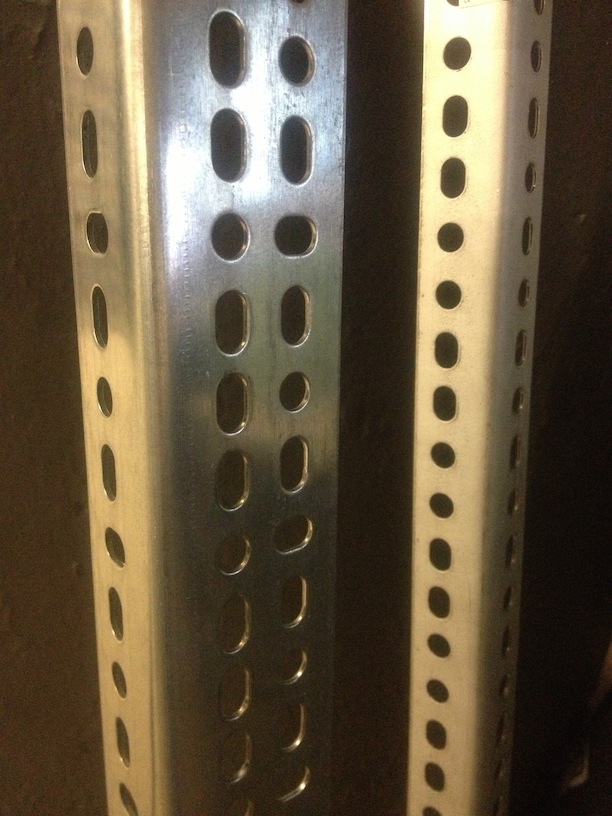
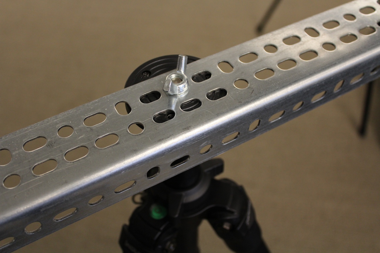
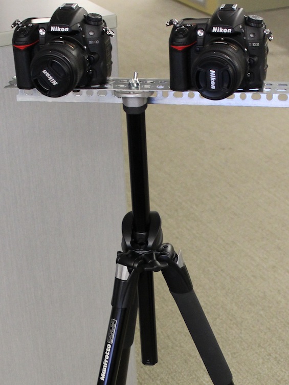
A DIY stereo bar can be made from various raw materials or by modifiying existing off-the-shelf hardware. Here we suggest creating a stereo bar from bracketing/shelving hardware such as that shown below. The ready-made slots and holes in the bracketing provide an easy solution for mounting cameras and for mounting the bar to the tripod. The ⅜” threaded mount on the tripod or articulated arm can fit through one of the holes and be secured in place with a wing nut. ¼” bolts can be inserted through the slots or holes in order to mount the cameras, and the camera position can be adjusted by choosing a different hole or slot. Note that the bolts must be long enough to thread fully into the camera mounting holes but not too long such that they cannot be firmly tightened against the stereo bar. We recommend that washers and/or rubber pads also be used for additional camera stability. Insert each bolt in turn through the hole or slot in the stereo bar and thread it into the bottom of the camera until secure. Note that minor adjustments to the position of the cameras will be made during the calibration process; the cameras can be roughly positioned at this time.
Picture: Metal bracketing purchased from a hardware supply store that could be used to create a stereo bar.
Picture: Metal bracketing cut to length and mounted on tripod with wing nut.
Picture: Cameras mounted on DIY stereo bracket.
