The Geometric Manager
- Antranig Basman
- Anastasia Cheetham
The Fluid "Geometric Manager"
The Geometric Manager is a Unit together with a collection of supporting utilities which supports geometric navigation and reasoning within a browser document. Here "geometric" represents a coordinate-based rather than a DOM structure-based understanding of the document. The Geometric Manager is housed in the framework file GeometricManager.js.
Overall functions of the Geometric Manager
The Geometric Manager has two main overall functions. Firstly, that of enabling "generalised" keyboard navigation against a free-form document layout. This allows sensible "heuristic" processing of directional (cursor-key based) navigation around a document without any assumptions on its structure, based solely on resulting pixel-based layout coordinates. Secondly, that of a "drop manager", to be used during a pointer-based dragging operation which is intended to service a "derangement" or "reordering" of the document structure (as distinct from an "activation"-oriented pointer dragging operation.
These functions are accessed through two principal APIs, firstly the method fluid.geom.projectFrom which implements the basic algorithm for geometric directional navigation, and secondly the overall Unit dropManager which is constructed via fluid.dropManager. The principal currency of the dropManager is a structure named geometricInfo which is described here:
The geometricInfo structure
The geometricInfo structure is the core representation for the "model" of the Geometric Manager - a client of the Manager reports its managed DOM nodes and their relationships in a structure of this form to the Geometric Manager, which then computes its own internal tables based on this structure and coordinate information derived from the DOM nodes reported in it.
Here is a sample instantiation of a geometricInfo structure, in this case the one appropriate for the simple LayoutHandlers:
{
    sentinelize: sentinelize,
    extents: [{orientation : orientation,
              elements     : dom.fastLocate("dropTargets")
              }],
    elementMapper: function(element) {
              return $.inArray(element, dom.fastLocate("movables")) === -1? "locked": null;
              }};
The elements of this structure will now be documented separately:
Name |
Type |
Description |
|---|---|---|
|
|
A flag indicating whether "sentinel regions" should be generated at the ends of each "extent" (see documentation below) |
|
|
A list of the "extents" to be managed - an extent is essentially an array of DOM nodes with an orientation |
|
|
An element "type mapper" which accepts a DOM node and maps it to a String representing its type. The String value currently may take on the value |
An element of the extents list is a record as follows:
Name |
Type |
Description |
|---|---|---|
|
|
The list of managed DOM nodes in this extent. These must be all sibling DOM nodes (that is, children of the same parent), although they need not be contiguous siblings. |
|
One of |
Represents the orientation of the DOM elements as rendered in the layout. |
|
DOM element |
The DOM element which is the parent of all the members of |
Top-level methods of the Geometric Manager
Name |
Type |
Description |
|---|---|---|
|
|
Inform the (stateful) Geometric Manager that the geometric info has changed, and that its previous cache of geometric information should be discarded and recomputed. |
|
|
Called on the start of a mouse drag operation which is recognised as that for a relevant "grab handle" for one of the managed DOM elements. The current dimensions of the relevant grab handle are reported, as well as the JQuery wrapped form of the originating event. A mouse move listener will be attached to the document for the duration of the drag. |
|
|
Represents that the drag operation has concluded. The mouse move listener will be unbound. |
|
|
An entry of type eventFirer which will receive notifications during a drag of a meaningful change in the "most appropriate" drop target for the current pointer position. |
|
|
Finds the "most appropriate" managed element (previously reported in |
Calculations performed by the Geometric Manager
The following diagram will help to visualise the calculations which are performed by the geometric manager, both for servicing pointer-based changes via the dropChangeFirer and directional (keyboard) navigation for projectFrom:
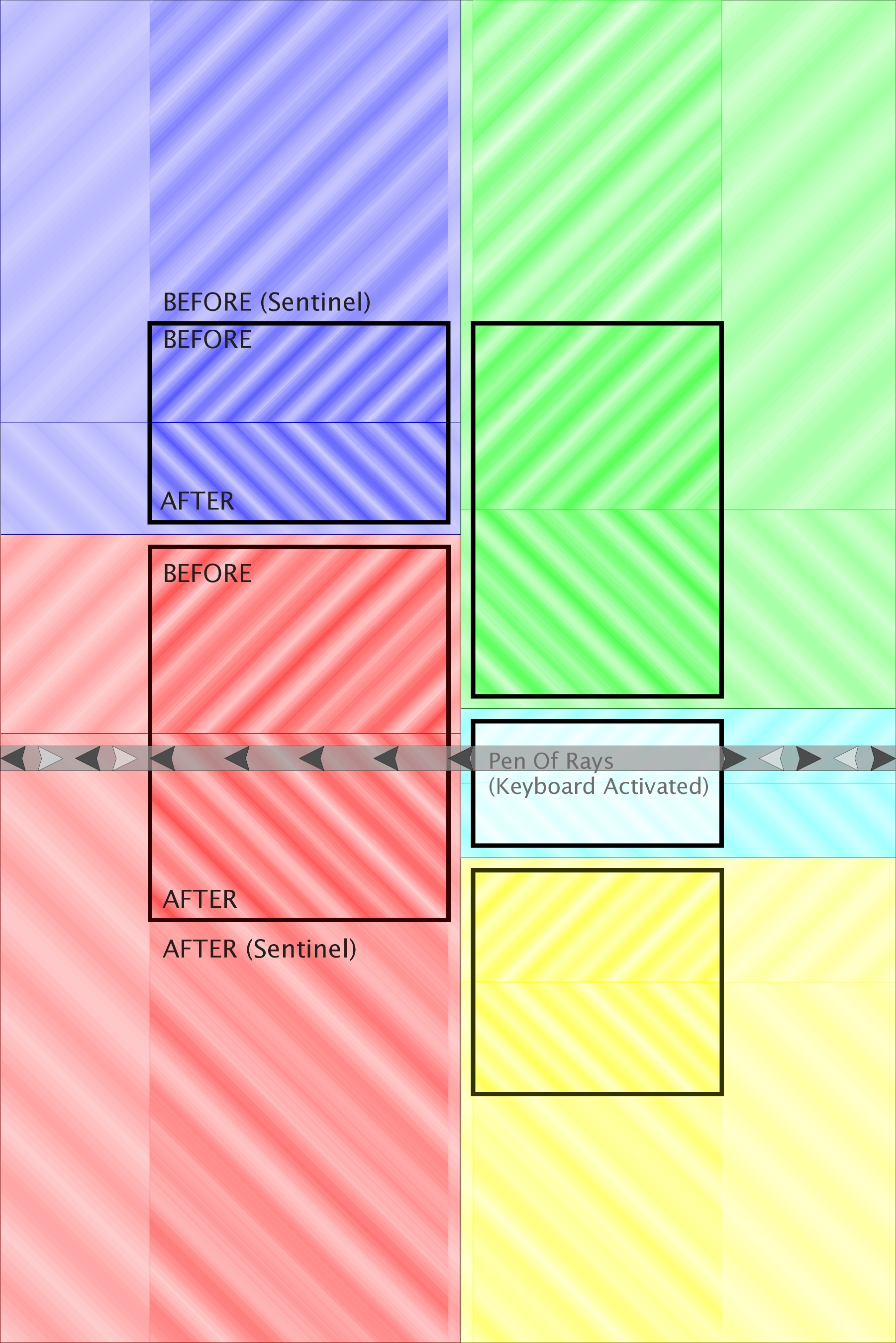
The managed elements themselves
Each of the darkest, centrally coloured areas (outlined in a thicker black line) represent the 5 basic DOM nodes supplied via geometricInfo. In this case, there were two "extents", consisting of two and three elements respectively, both with the VERTICAL orientation - this layout is the one taken from the uPortal Sample using the ModuleLayout with the Reorderer component.
The interior drop zones
The "somewhat darker coloured" regions correspond to the drop zones computed from these elements. To start with, two zones are computed within each element, in this case allocating the top half of each element as a zone resulting in a drop BEFORE the target element and the bottom half for a drop AFTER. For all drop zones, the direction of diagonal shading represents the polarity of the zone - BEFORE zones are shaded diagonally from bottom left to top right, whereas AFTER zones are shaded diagonally frop top left to bottom right.
Sentinel zones
The "somewhat lighter coloured" regions which appear above and below entire columns (extents) are sentinel zones, which are synthesized from the overall extent to ensure that the zone structure respects an overall columnar strategy - visually the effects would be unexpected if a pointer/keyboard position within a "column" in such a layout did not result in a target chosen within the column. The sentinel zone is as wide (high, for a HORIZONTAL extent) as the end element in the extent, and is "extremely high" (a sentinel dimension of 10000 pixels is arbitrarily chosen to ensure that the sentinel is "sufficiently big" without causing numerical difficulties). The sentinel zones also inherit the polarity BEFORE/AFTER of their neighbouring interior drop zones.
"Regions of attraction"
For pointer-based navigation, the complete set of drop zones result in a tesselation of the plane into "regions of attraction", assigning to each location (pointer x,y coordinate) the nearest drop zone. This nearest distance is computed as the shortest distance between the pointer position and the rectangle of the drop zone, using the algorithm MINDIST(p,R) which for ready reference is presented in these McGill University CS Lecture Notes. These zones of attraction are shown in the faintest colours - as can be seen, these completely fill the plane with colour, and generally pass along the bisectors of the spaces between drop zone rectangles (although in more skew layouts, and especially those without sentinels) this pattern would be more complex. Note also that each attraction region associates a polarity BEFORE/AFTER with each plane position as well as associating it with one of the managed elements (thick black outlines).
Locked zones
If an element has its class reported as "locked" by the elementMapper, some of its derived drop zones may also become labelled as "locked". To start with, the zones between any two adjacent "locked" elements will be marked as "locked". Secondly, the sentinel zone above a locked element at the start of its extent will also be marked as locked. Locked zones will be excluded from the list considered for the return of the closestTarget method called during a mouse drag, but if a "locked" zone is closer to the pointer than the closest zone found and reported, this will be flagged on the returned structure.
Directional (keyboard) navigation - the "Pen of Rays"
The cyan portlet (2nd in the right column) is specially activated to illustrate the algorithm used for computing adjacent targets via rectangular projection (suitable when servicing a cursor key navigation request from a portlet). This is represented geometrically by projecting a "Pen of Rays" from the upper portion of the activated element. This is a rectangular region, of "sentinel width" (height, for a HORIZONTAL orientation extent), which extends between 1/8 and 3/8 of the height of the target element. The most desirable candidates for the navigation are those elements which intersect this rectangular pen. The pen dimensions were chosen to ensure that i) the pen lies wholly within the BEFORE region of the element, and ii) scales along with the element dimensions in the overall layout. It is not simply a line to guard agains the risk of the pen "slipping between" rectangles of the most closely neighbouring elements due to gaps in the layout and undesirably intersecting further away elements as the nearest intersection.
The "Pen of Rays" gives rise to a priority structure for navigation to elements which are on and near it. The first priority is given to the nearest elements which intersect it, in the direction of the desired navigation, but excluding those which share any projection of the element itself onto the pen. Therefore in this case, the green and yellow portlets are permanently excluded from all calculations, since they intersect the cyan portlet's own projection onto its pen. This navigation may "wrap" to the opposite side of the layout if no elements are found immediately in the desired direction - this is represented by the two sets of grey arrows shown within the pen. The darker arrows represent the search through the "most neighbouring" regions, which if it wraps to the opposite layout side, is shown by the lighter-coloured arrows. In this case, both left and right directional cursor navigation would select the larger red portlet to the left of the cyan portlet.
If no layout elements at all intersect the pen, the search will be widened to other elements, picking those by priority which have the smallest perpendicular distance to the pen, again considering the exclusion of those which overlap the element's intersection with the pen (i.e. zones like the green and yellow ones are always excluded from any search). Unlike the pointer-based navigation, it is therefore possible for this directional navigation to find no target at all, in the case all are excluded by this "projection intersection rule". However, this algorithm does assign a "plausible ordering" on all the remaining zones (in this case, the blue and red ones). This ordering is a kind of lexicographic ordering based on the points in the plane.